 Español
  English (UK)
This is a quick example of how to use websockets in an ESP8266 device. I wanted to experiment with websockets and this was a simple way to do it. The device runs the websocket server and its code is very similar to what you can find in this example. On the other side, the client is a Qt (QML) application. I think QML is an easy way of developing applications and the advantage is that you can use the same code in a smartphone or a desktop PC. If you prefer, before reading this article you can find the source code repository here.
Requirements
- This source uses Arduino IDE and its standard libraries
- Additional libraries: arduinoWebsocket
- QT creator IDE for the client application
Hardware components
- NodeMCU 0.9/1.0
- An RGB Led
- A computer or smartphone to run the client application
Description
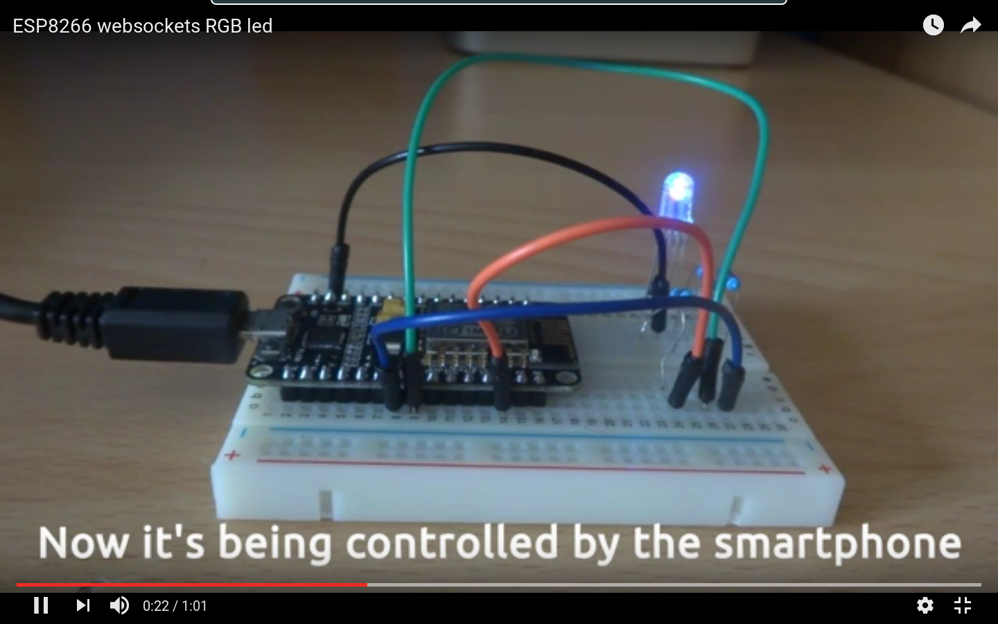
The Qt application shows a color picker that sends the current RGB color value through a websocket to the NodeMCU device. So, you can see how the colors change as you move your finger on the screen. Regarding the device, the circuit is very simple and can be found in other projects on the web.I use three 220 ohm resistors but it is preferable to use different values according to the information of the RGB led specifications. Because of that, the colors I get are not very accurate, It works well with red, green, blue and magenta but as an example, I couldn't get yellow. You can read about this for instance here

When the code is executed the led shows a red color while the WiFi access point is set. Then, when is ready, the led turns into green. Due to the NodeMCU works as an AP,it is necessary to connect to that wireless network from the smartphone (or the computer) OS. The default WiFi network parameters are the following:
- SSID: ESP8266-RGB
- Password: rgb12345
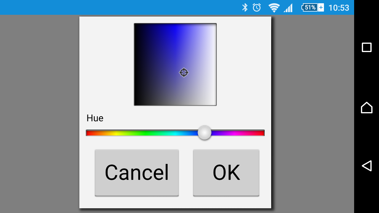
After connected to this network you can launch the client application. As you can see the app is very simple and only displays a color picker
The code
QT Client
Now, let's see the important things in the QT source. Nowadays, a QT application has usually C++ and QML code. As you can imagine, the idea is to have the presentation layer in QML and keep the control in the C++ files. First, in the C++ main file we launch the main QML file which draws the window and its elements. Then, we look for the QML root object (the ApplicationWindow component) and we point to it in our QObject item. Now, we create an instance of our web service class giving to the constructor the address of the web socket server. As we have our item object representing the QML side we can connect our C++ client class to it, making possible to send the QML color picker value to our class slot
int main(int argc, char *argv[])
{
    QCoreApplication::setAttribute(Qt::AA_EnableHighDpiScaling);
    QGuiApplication app(argc, argv);

    QQmlApplicationEngine engine;
    engine.load(QUrl(QLatin1String("qrc:/main.qml")));

    QObject *item = engine.rootObjects().at(0);

    WSClient client(QUrl(QStringLiteral("ws://192.168.4.1:81")));
    QObject::connect(&client, &WSClient::closed, &app, &QCoreApplication::quit);

    QObject::connect(item, SIGNAL(changeColor(QString)), &client, SLOT(onColorChanged(QString)));

    return app.exec();
}
Now it's time for the WSClient class. The following code shows how the websocket client is created. It is an unsecured socket (the arduinoWebsocket library does not provide a wss (SSL) server). There are two important signals; the one that is triggered after the connection is established and the one that occurs when is disconnected. After that the websocket is opened using a valid url.
    m_url = url;
    m_webSocket = new QWebSocket("QT App",QWebSocketProtocol::Version0);
    m_webSocket->ignoreSslErrors();
    connect(m_webSocket, &QWebSocket::connected, this, &WSClient::onConnected);
    connect(m_webSocket, &QWebSocket::disconnected, this, &WSClient::onDisconnected);

    QNetworkRequest req(m_url);
    req.setRawHeader("Connection","keep-alive, Upgrade");
    m_webSocket->open(req);
The onConnected slot is the responsible of changing the led color again to show that the client is connected to the NodeMCU. In other words, the green color will be changed to red by this slot. The RGB code is transmitted through the websocket to the NodeMCU. In the device (explained later), the code is split to obtain each of the red, green and blue values which are converted to integers and sent to the corresponding PWM pin. The new signal-slot connection is not important and it is used to print debug messages.
void WSClient::onConnected()
{
    qDebug() << "WebSocket connected";
    connect(m_webSocket, &QWebSocket::textMessageReceived,this, &WSClient::onTextMessageReceived);
    m_webSocket->sendTextMessage(QStringLiteral("#ff0000"));
}
In a similar way we use the onDisconnected slot to print debug messages reporting the reason of the disconnection.
void WSClient::onDisconnected()
{
    qDebug() << "Disconnected " << m_webSocket->state();
    qDebug() << m_webSocket->closeReason();
}
Finally, there is a slot to send the color selected in the color picker through the websocket.
void WSClient::onColorChanged(QString color)
{
    m_webSocket->sendTextMessage(color);
    qDebug() << "Color changed to " << color;
}
Regarding the QML source, the important parts of the main.qml file are explained here. The ApplicationWindow is the root object of the QML file and so, is the object we get in the c++ main file to make the connections. The changeColor signal signal is defined to connect this QML object with the C++ WSClient object (as we did in the main.cpp connection). The signal is emmitted from the ColorDialog onCurrentColorChanged slot, including the RGB value to send to the device
[...]
ApplicationWindow {
    id: window
    visible: true
    width: 640
    height: 480
    title: qsTr("Hello World")

    signal changeColor(string msg)

    ColorDialog {
        id: colorDialog
        title: "Please choose a color"
        onAccepted: {
            console.log("You chose: " + colorDialog.color)
            Qt.quit()
        }

        onCurrentColorChanged: {
            window.changeColor(currentColor)
        }
        [...]
    }

}
NodeMCU code
As said before, the arduino sketch is very similar to the example found at the arduinoWebsocket project. We first define which pins of the device to use
[...]
#define RED_PIN 4  //(D1)
#define GREEN_PIN 14 //(D2)
#define BLUE_PIN 12  //(D3)
Now we launch the web and websocket servers:
ESP8266WiFiMulti WiFiMulti;

ESP8266WebServer server = ESP8266WebServer(80);
WebSocketsServer webSocket = WebSocketsServer(81);
The next code is the definition of event that will handle the received messages. For the color codes we have to shift the data to get the red, green and blue values separately.
void webSocketEvent(uint8_t num, WStype_t type, uint8_t * payload, size_t lenght) {

    switch(type) {
        case WStype_DISCONNECTED:
            Serial.printf("[%u] Disconnected!\n", num);
            break;
        case WStype_CONNECTED: {
            IPAddress ip = webSocket.remoteIP(num);
            Serial.printf("[%u] Connected from %d.%d.%d.%d url: %s\n", num, ip[0], ip[1], ip[2], ip[3], payload);

            // send message to client
            webSocket.sendTXT(num, "Connected");
        }
            break;
        case WStype_TEXT:
            Serial.printf("[%u] get Text: %s\n", num, payload);

            if(payload[0] == '#') {
                // we get RGB data

                // decode rgb data
                uint32_t rgb = (uint32_t) strtol((const char *) &payload[1], NULL, 16);

                analogWrite(RED_PIN,    ((rgb >> 16) & 0xFF) <<2); //PWM on a ESP8266 is from 0 to 1023, so the last <> 8)
                analogWrite(GREEN_PIN, ((rgb >> 8) & 0xFF) <<2);
                analogWrite(BLUE_PIN, ((rgb >> 0) & 0xFF) <<2);
            }

            break;
    }

}
After setting up the WiFI Access Point we start the websocket server and link the previous event function.
  [...]

void setup()
{
  [...]

  // start webSocket server
  webSocket.begin();
  webSocket.onEvent(webSocketEvent);
Then, the MDNS service is configured and the html page that can be used to control the device is included. After that, we can change the color to green. Remember that the PWM limits for the NodeMCU are from 0 to 1023, differing from Arduino (0 to 255).
if(MDNS.begin("esp8266")) {
    Serial.println("MDNS responder started");
}

// handle index
server.on("/", []() {
// send index.html
// The html code is here
[...]
server.begin(); // Add service to MDNS
MDNS.addService("http", "tcp", 80);
MDNS.addService("ws", "tcp", 81);
analogWrite(RED_PIN, 0);
analogWrite(GREEN_PIN, 1023);
analogWrite(BLUE_PIN, 0); }
The main loop is just for handling the html and websocket servers
void loop()
{
  webSocket.loop();
  server.handleClient();
}
The demo
I uploaded a video where you can see how everything works:
Instead using the QT application, another option is to launch in a web browser this URL: http://esp8266.local (if this doesn't work try http://192.168.4.1). You will notice three sliders corresponding with the RGB values. Just change them and you will see the new color in your led.